Introduction
I am renting an 1b1b apartment in Silicon Valley. It is not a big apartment and yet has many confusing power switches which were obviously designed by qualified project managers.
The wall switch near the door controls one of the outlet in the living room. I connected it to a floor lamp so that I can turn on the light when I got home. If I want to turn it off, however, I have to leave my comfortable sofa and walk to the door to turn the light off. Not saying I am a lazy person, but home is supposed to be a place to make people feel lazy.
Another thing that bothers me is that I often carry a lot of things (e.g. groceries) when I enter or leave the apartment, making myself very hard to take out the key to lock/unlock the door. I just hope that the door can be smart like it in some modern cars so that it can lock/unlock itself.
I also have a lot of entertainment devices such TV, projector, sound bar, PS4. It’s frustrated every time to have at least 3 remotes on hand and open them one by one.
That’s why I started my smart home project which based on the following high-level goals I want to achieve.
High-level Goals
- Turn on/off all major lights in the apartment by just saying “Turn on/off the light”
- Lock/unlock the door without using my key, or even my attention
- Open/close blinds automatically or by sound control
- Open/close window with sound
- Control A/C and fan with sound
- Wake me up with different songs every day
- Control TV, projector, sound bar, Apple TV, PS4 without using tons of remotes
Hardware
- Raspberry Pi 3 Model B
- RioRand(TM) 433MHz RF transmitter and receiver
- Etekcity Wireless Remote Outlets
- Echo Dot (2nd Gen)
- MagicW 38KHz IR transmitter and receiver
- Futaba S3003 Servo
- 2N3904 Transistor
- Breadboards (400 pin)
- ESP8266 NodeMCU modules
- Jump wires
- Lego bricks
Infrastructure
My final plan is to build the smart IOT system with Amazon Echo Dot and Siri as control inputs, Raspberry Pi 3 as control control dispatch center, and ESP8266 NodeMCU module as control terminal. This part is just for reference as a lot of things might change with time.
Setup Raspberry Pi
- Make an order of all devices via Amazon. Received after two days.
- Download Raspbian. Note that no need to burn image to USB drive described in the docs. Just unzipping the file and copying and pasting everything to the USB drive.
- Connect Raspberry PI to keyboard, monitor via HDMI port, mouse.
- Install Raspbian Jessie.
- Setup Wifi Connection and enable SSH. Change the computer name to “pi”. Change the default password.
- Test SSH connection:
$ ssh pi@pi.local - Install Nodejs:
$ sudo apt-get update$ curl -sLS https://apt.adafruit.com/add | sudo bash$ sudo apt-get install node
- Install Vim:
$ sudo apt-get vim - Install Python 3.6.1 (optional):
$ sudo apt-get update$ sudo apt-get install build-essential tk-dev libncurses5-dev libncursesw5-dev libreadline6-dev libdb5.3-dev libgdbm-dev libsqlite3-dev libssl-dev libbz2-dev libexpat1-dev liblzma-dev zlib1g-dev- $ wget https://www.python.org/ftp/python/3.6.1/Python-3.6.1.tar.xz
- $ tar xf Python-3.6.1.tar.xz
- $ cd Python-3.6.1
- $ ./configure –enable-optimizations
- $ make
- $ sudo make altinstall
Homebridge - Siri
Install Homebridge:
$ sudo npm install -g --unsafe-perm homebridge
Install homebridge-cmdswitch2 so that you can connect Homebridge to anything.
Setup run at boot following official guide.
Open iPhone and “Add accessory”, select Homebridge.
Amazon Echo Dot
Instead of using Skills, I use Fauxmo, which is a piece of code pretending itself to be a WeMo device. So that I can just say “Alexa, do something” instead of “Alexa, tell x to do something”.
Just mkdir in a workspace, and initiate the directory to a npm directory.
$ npm install fauxmojs ip --save
Using the following code to create a configuration file. It’s very similar to the config file of Homebridge. The actual control commands are located in handler() functions. We will add those later.
const FauxMo = require('fauxmojs');
const ip = require('ip');
const { spawnSync } = require('child_process');
const request = require('request');

let fauxMo = new FauxMo({
  ipAddress: ip.address(),
  devices: [{
    name: 'Living Room Light',
    port: 11000,
    handler(action) {
      if (action === 'on') {
        // do something
      } else if  (action === 'off') {
        // do something else
      }
    }
  }]
});

console.log('started...');
ESP8266 NodeMCU module
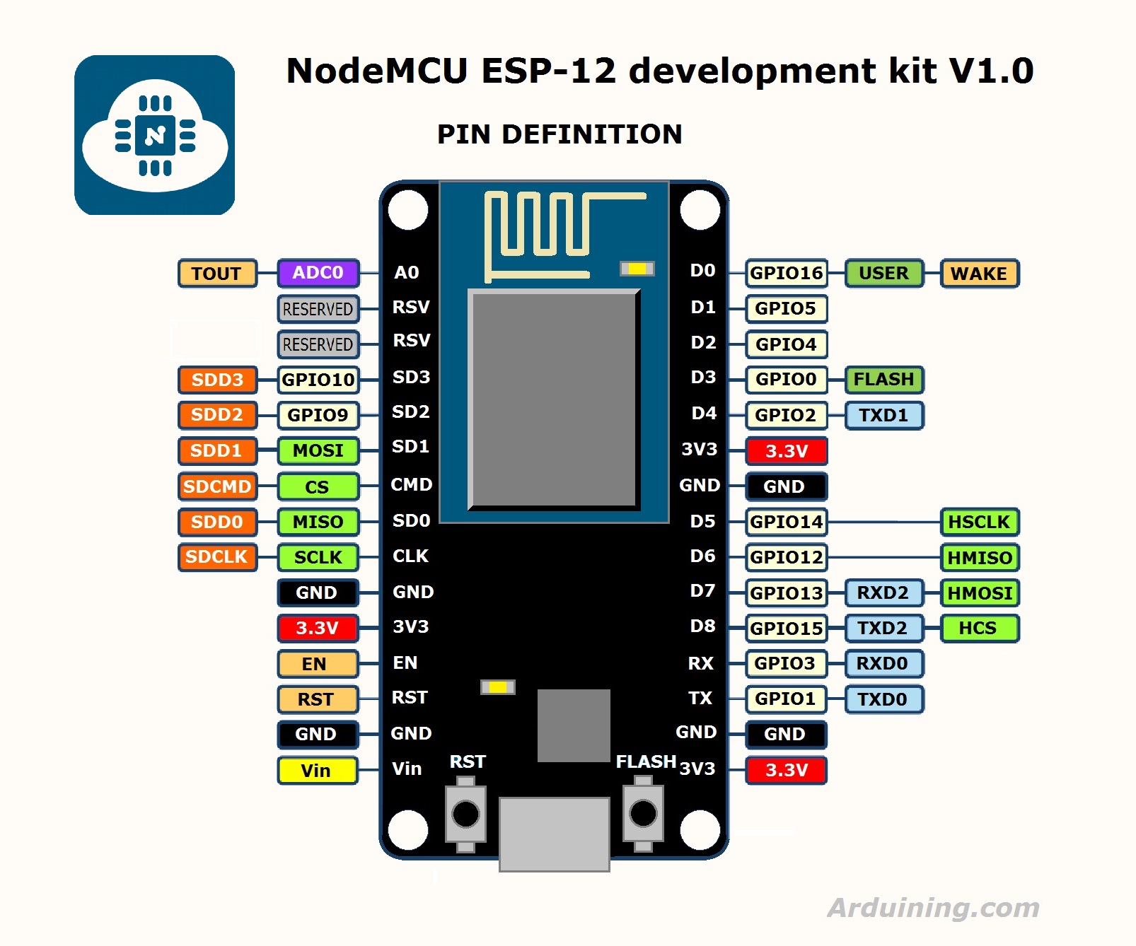
First, you need a map for this:
Download an install drivers mentioned here and here.
Getting a USB-to-mini USB data sync cable, and connecting NodeMCU with Mac.
Open Arduino IDE, download libraries for NodeMCU (Follow guide https://github.com/esp8266/Arduino). Restart IDE. There should be two items in “port” section in the menu: bluetooth and something like SLAB_USBtoUART. Open an example file from the menu, click “upload”, the blue LED will blink. Click a button at the top right corner of the IDE window to open the console, and select the correct channel number to see the logs.
Lights
The idea of controlling lights is using cheap RF remote outlets and RF transmitter. You can buy a set of 5 remote outlets made by Etekcity for $30 at Amazon, while the cheapest Siri enabled outlet is at least $20.
Plugging a RF outlet into wall, hacking the remote on/off RF code, then using Siri or Alexa to control.
First connect the RF transmitter and receiver to Raspberry PI. Basically they are both VCC to 3.3V, Ground to GND, and data to GPIO pin.
Install wiringPi.
Using rf_pi. Download it to Raspberry PI.
$ git clone https://github.com/n8henrie/rf_pi.git
$ cd rf_pi

# Edit files with your pin values, etc.
vim RFSniffer.cpp # edit to change your pin number if needed
$ vim send.cpp # edit to change your pin number / pulse length if needed

# Will ask for sudo privileges for the `setcap` step and will give an (ignored)
# error if you didn't install libcap2-bin:
$ make
Start recording:
$ ./RFSniffer
Click buttons in remote and save the code somewhere for later use.
Test sending:
$ ./send 123456
Integration
For Siri, add the following commands to config.json:
{
  "on_cmd": "/home/pi/workspace/rf_pi/send 5272835",
  "off_cmd": "/home/pi/workspace/rf_pi/send 5272836"
}
For Alexa, add the following:
const { spawnSync } from 'child_process';
// ...
if (action === 'on') {
  spawnSync('/home/pi/workspace/rf_pi/send', ['5272835'], { encoding: 'utf8'});
} else if (action === 'off') {
  spawnSync('/home/pi/workspace/rf_pi/send', ['5272844'], { encoding: 'utf8'});
}
A/C
A/C remote is using Infrared Remote signal. Need to do similar to lights. Unlike RF, IR transmitting requires directional action range, meaning that you have to point the IR Led bulb to the device. In such case, however, the position of the Raspberry PI is limited.
So I discovered a small and cheap WiFi Enabled module called ESP8266. The idea is deploying several ESP8266 in the room for different devices. Connecting IR emitter to them. Sending commands from Raspberry PI using HTTP requests.
Setup Arduino IDE
In this part, Raspberry PI is not needed. Just need a computer. For MacOS Sierra users, need to download a CH340 driver. Install the driver, and restart the computer.
Download Arduino IDE and install. In “Manager Libraries”, enter “Esp8266” and install the NodeMCU library. Using a data cable (micro USB to USB) connecting ESP chip and the Macbook. In the menu, selecting “Tools” and “Boards”, selecting “NodeMCU 1.0”. In “Port”, selecting the second item (not Bluetooth port).
Open a example code in the menu, and run “Upload” to test that everything works.
IR Recording
Put the NodeMCU module into the breadboard. Connecting IR Receiver VCC to 3.3V, GND to GND, Data to D5, which is GPIO 14 pin. You should always have a NodeMCU pin map as guidance.
Using IRremoteESP8266 package, download and move the unzipped folder to <path>/Arduino/Libraries. Restart the IDE. There will be something more in the examples. Open IRrecvDumpV2.ino example. Click top right corner open Serial Monitor. Switch to channel 115200 (or whatever in the code, with something like Serial.begin(115200)). Upload the code.
Pointing A/C remote to the receiver and click power button. Something will show up in the Serial Monitor. There are multiple cases. In my case, it shows “UNKNOWN”, and prints some raw data. It is an unsigned int.
uint16_t acPowerRawData[37] = {8500,4300, 550,1600, 550,1600, 550,1600, 500,600, 550,1600, 550,600, 550,1600, 550,1600, 500,4300, 550,1600, 500,1650, 550,550, 550,1600, 550,550, 550,550, 550,550, 550,550, 600};
Save it somewhere for later use. If it is “NEC”, just save the one int code.
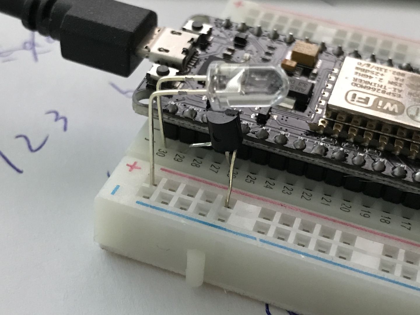
IR Sending
Connecting LED and transistor described here. To make the board simple, you don’t have to follow it exactly. A better option is to use the left bottom corner pins (3.3V, Ground, and D8). So that no need for jumper wires.
Open a new Arduino editor, using the sample code. The setup() basically connects to the WiFi, runs a simple HTTP server, and listen to a path called “/ac_power”. Change the rawData to actual array you got from previous step.
To send the raw data of A/C power:
irsend.sendRaw(acPowerRawData, 37, 38);
The second parameter is the length, the third one is the HZ. It is usually 38 kHz for most home devices.
Integration
For Siri, change the command of A/C on and off to curl http://ac.local/ac_power.
For Alexa, change the handler function to:
const request = require('request');
// ...
request.get('http://ac.local/ac_power');
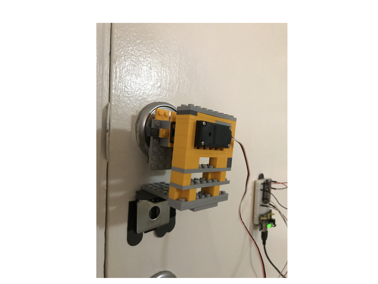
Door Lock
I always have a challenge when I tried to open the door after returning from work and gym, holding a duffle bag and some food. It’s quite difficult to grab the key and insert it into the key hold accurately. I want to use voice control to open the lock and allow me to enter my apartment without keys. However, door key has a security issue. Thus I don’t hope people can enter my apartment by asking “Alexa, open the door” freely.
There are some products in the market that allows user to control their door locks with phone. But 1) they are really expensive, 2) user has to use their apps, and 3) the installation is complicated.
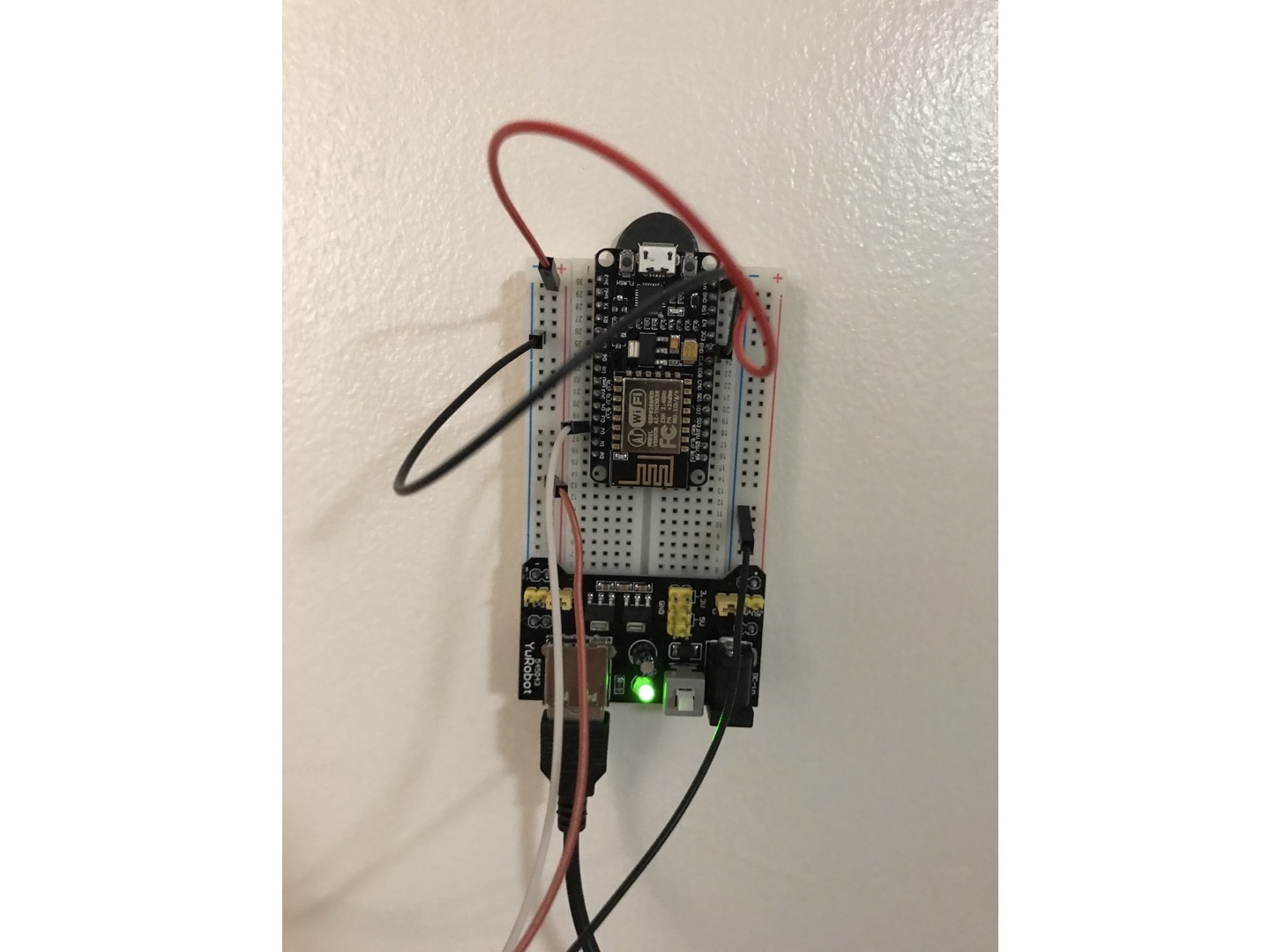
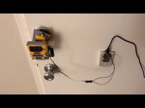
The solution is to create a robotic handle using Lego bricks and a standard 5V servo. The servo is controller by another ESP8266 module, which starts a simple HTTP server and waiting for requests from the Raspberry Pi. THe ESP8266, however, only outputs 3.3V. Even though the servo still works, but the power is low. I might need to connect it to an external power source, or move the Raspberry Pi to somewhere near the door.
Creating a new file in Aruino IDE:
#include <ESP8266WiFi.h>
#include <WiFiClient.h>
#include <ESP8266WebServer.h>
#include <ESP8266mDNS.h>
#include <Servo.h>

#define DELAY_BETWEEN_COMMANDS 1000
#define LOCK_DOOR 24
#define UNLOCK_DOOR 134

Servo myservo;

const char* ssid = "";
const char* password = "";
const char* hname = "lock";
int state = LOCK_DOOR;

ESP8266WebServer server(80);

const int led = BUILTIN_LED;

void setup(void){
  myservo.attach(4); // GPIO 4 D2
  myservo.write(LOCK_DOOR);

  pinMode(led, OUTPUT);
  digitalWrite(led, 1);
  Serial.begin(115200);
  WiFi.begin(ssid, password);
  WiFi.hostname(hname);
  Serial.println("");

  // Wait for connection
  while (WiFi.status() != WL_CONNECTED) {
    delay(500);
    Serial.print(".");
  }
  Serial.println("");
  Serial.print("Connected to ");
  Serial.println(ssid);
  Serial.print("IP address: ");
  Serial.println(WiFi.localIP());

  if (MDNS.begin(hname)) {
    Serial.println("MDNS Responder Started");
  }

  server.on("/door_lock", [](){
    myservo.write(LOCK_DOOR);
    state = LOCK_DOOR;
    server.send(200, "text/plain", "Door locked");
  });

  server.on("/door_unlock", [](){
    myservo.write(UNLOCK_DOOR);
    state = UNLOCK_DOOR;
    server.send(200, "text/plain", "Door unlocked");
  });

  server.begin();
  Serial.println("HTTP Server Started");
}

void loop(void){
  server.handleClient();
}
LOCK_DOOR and UNLOCK_DOOR are two constants of the angles the servo should use to open and close the lock. To test if it works, visit the following two URLs in the browser:
http://lock.local/door_lockhttp://lock.local/door_unlock
At last, setting up Homebridge to send a curl command when I say “Siri, open the door”. No need for Alexa because you don’t want random people to open your door by shouting outside of the apartment.
Click to see a demo hosted on YouTube:
You can find all code here.